“Sine City”- San Marcos Creek Development Project
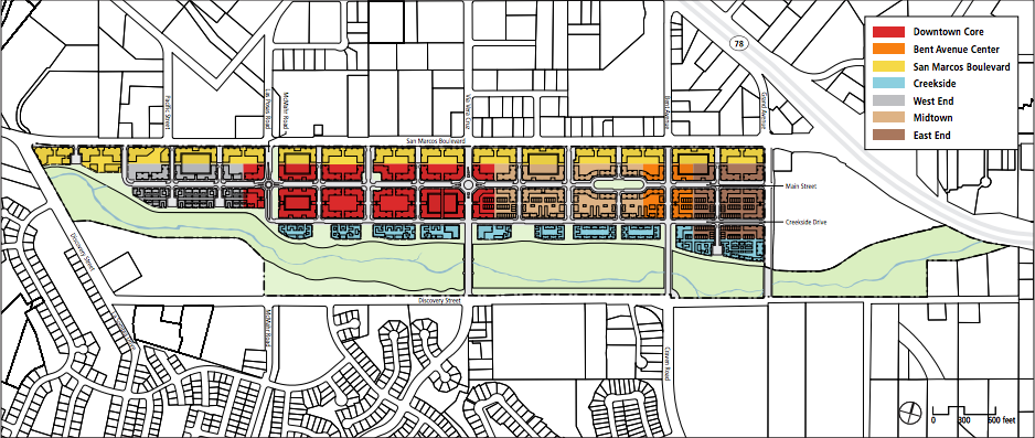
San Marcos currently has a plan in the works to design and construct a "downtown" area called the San Marcos Creek District in the few blocks south of San Marcos Blvd., bordered by Discovery St. to the west and the CA-78 freeway to the east. In this project, we worked in groups with the specific plan laid out by the city to plan layouts for the various lots in the Creek District. The District is sectioned off into various zones, each with a different purpose. For example, two zones - the Downtown Core and Bent Avenue Center - are meant to be very urban, with retailers and businesses taking up most of the space, whereas three others - West End, Midtown, and East End - are intended for a more suburban feel, with multi-family housing and small-scale retailers. We had to take the requirements of our lots, which varied by zone, into account, as well as the city's intention for each lots, so there was a large aspect of urban planning and architectural design incorporated into the project. The main purpose of the project, though, was to use trigonometry and the golden ratio in a practical application. We used the latter in our architectural designs, and we used the former in our initial site mapping and in designing awnings for our buildings' windows.
The first assignment of the project was for each group to walk to their lot and map out what was already there. For many groups, it was difficult or impossible to freely walk around and take measurements, or impossible to measure the heights of very tall structures. Thus, we had to use triangulation to approximate some measurements. We did this using protractors with their straight edges fixed to a sighting tube - in this case, a straw - and strings tied to their centers with weights hanging down. These tools allowed us to point the protractors at the tops and bases of structures and measure their angles of elevation. We could then create triangles with certain known angles and sides, and use the laws of sines and cosines to solve for the necessary information.
The next step was to plan our site layouts. As it turned out, my group's lot was on the site of the Promenade at Creekside, an affordable-housing apartment complex that is already under construction for the Creekside District, but we decided that we would design our own building anyways. Taking into account the intentions for our lot, we determined that an apartment building would, in fact, be the best use of our space, and so we designed our own apartment building. For this, we had to take several factors into account: chief among them were required building frontages, setbacks, where ground floor residential was allowed, and parking spaces. There was a requirement for the percentage of each side of our lot that needed to be fronted by the building - 50% to the east and west, and 75% to the north and south - so we designed our building to run around the perimeter of our lot with a parking area in the middle. Next, we had to consider the setbacks. To the north, west, and east, the building façade had to be at the property's edge except if it was ground-floor residential, in which case it had to be 5 feet back from the edge. To the south, the façade had to be between 5 and 20 feet from the edge. Third, the east half of our lot was ground floor residential permitted, and the west half was permitted except at intersections; since there was only one intersection on the west half of our lot, we had to place our lobby at that intersection. Finally, there were minimum numbers of parking spaces required for each apartment in our building, depending on the sizes of the apartments. After estimating the portions of our total apartment space that would be allocated to each apartment size, we were able to come up with a value for the number of apartment square footage per required parking space, and when we took into account the area we had for parking, we realized that we could only have two floors on our building. This was a key realization, since we had originally designed four floors. We could have increased our parking area by designing a parking garage, but we were concerned with the aesthetic problems of such a structure, so we decided to have all of our parking at ground level.
After planning the layout to account for all of the requirements, we had to design the building façades, including the windows, awnings, and any arches we wanted to have. This was where we incorporated trigonometry and the golden ratio. We had previously looked at sunpath diagrams to measure the angle of the sun at 2pm on the winter and summer solstices, so using trigonometry, we were able to design awnings that would leave the windows in full sun during the winter but cast them in full shade during the summer. The purpose behind doing this was to minimize heating and cooling costs in the building. In addition, we calculated the measurements so that there was a golden ratio between the top of each window and the bottom of its floor, and the top of each window and the top of its floor. Each window was shaped as a golden rectangle. We also had a number of arches all over our building, and we designed those so that there was a golden ratio between the straight sides and the heights of the curves.
The final step was to laser-cut a basic model of our building. We had already designed our building using SolidWorks, a CAD program that I had access to from robotics, so this was an easy matter. We created .dxf files of each face of our building and put those into the laser cutter software via Adobe Illustrator. Below are some pictures of our laser-cut model, our CAD model, and our exhibition.
In all honesty, I had a sufficient understanding of trigonometry before this project began that, aside from new practical applications for trigonometry, there wasn't a whole lot math-wise that I could learn from this project. I did, however, learn how to read a sunpath diagram, which was pretty neat, and I learned how to take zoning requirements into account when designing buildings. It's actually pretty difficult; just comprehending all of the requirements is hard enough, and trying to implement them all is even harder. This project was good design experience for me, and as a future engineer, I plan to be doing a lot of design work later in life.
My favorite aspect of this project was the CAD work. That was my main contribution to this project. I am the lead CAD designer for HTHNC's robotics team, so I have extensive experience using SolidWorks, and I am proud of the result of my efforts on that front. I think that, while our wooden building model did a good job of giving audience members in our exhibition a sense of the scale of our building, the CAD model was an excellent visual representation of the complete lot design. In this project, I learned the value of breaking problems up into small chunks and solving them one at a time. If our group had tried to take all of the design requirements into account at once, it would have been overwhelming. Instead, we took the requirements one at a time and simply adjusted our design to make it fit each requirement, and we eventually ended up with a design that met all of the requirements and of which we were proud. Taken in this manner, the requirements were fairly straightforward.
In the exhibition, I and one of my group members stood by our wooden model and explained our project to visitors. Our third group member was standing at a separate booth with a portfolio of our work and our CAD display, and we usually directed visitors to him after we were finished explaining the building design and model. It was interesting hearing visitors' feedback during the exhibition, and realizing what we hadn't thought of earlier. There was one instance, for example, where I explained our parking dilemma and why we couldn't have more than two floors to one visitor, and her immediate suggestion was to have underground parking. It was such a simple solution, yet no one in our group had thought of it. If we could do this project over again, I think we would all agree that underground parking would have been the best way to go.
